Winnebago wiring diagram 5af725d5e9131.gif.
1988 Operator Manuals. To download the operator manual for your vehicle, simply click on the appropriate link below. This information is provided as a convenience to Winnebago Industries motor home owners. When your vehicle requires parts and/or service, you should contact your local Winnebago Industries dealer. Your dealer has access to the ...
Oct 8, 2022 · The Winnebago Wiring Diagram 5af725d346448 Gif 4 is one such diagram that helps ensure the smooth operation of the motorhome's electrical system. This diagram contains the information needed to make sure that all elements of the electrical system are working optimally, from the battery to the fuse box and beyond. 2005 Journey/Meridian P32T Wiring Diagram Book. 110 Volt Load Center/Auto Transfer Switch. AC/Heat/EMS Wiring Diagram. Antenna Installation, Radio and CB. Auto Lamps Wiring Diagram. Automotive Wiring Diagram. Backup Monitor Installation. Body, 110 Volt Wiring Diagram. Body, 110 Volt Wiring Installation. Body, 12 Volt Wiring Diagram. Body, 12 ... 06-16-2013, 06:21 AM. # 2. trackman. Senior Member. Join Date: Oct 2011. Posts: 1,136. Go to Winnebago Industries and click on the wiring diagram tab. Has a complete list. You can get there on google by typing in Winnebago Brave Wiring Diagram.2005 Voyage/Sunrise F35A Wiring Diagram Book. 110 Volt Load Center/Auto Transfer Switch. Antenna Installation, Radio and CB. Auto Lamps Wiring Diagram. Automotive Wiring Diagram. Backup Monitor Installation. Body, 110 Volt Wiring Diagram. Body, 110 Volt Wiring Installation. Body, 12 Volt Wiring Diagram.
1984 Operator Manuals. To download the operator manual for your vehicle, simply click on the appropriate link below. This information is provided as a convenience to Winnebago Industries motor home owners. When your vehicle requires parts and/or service, you should contact your local Winnebago Industries dealer. Your dealer has access to the ...Oct 11, 2022 · The Winnebago Wiring Diagram 5af725d346448 Gif 4 is a valuable resource for any Winnebago owner. It provides easy access to essential wiring information for the vehicle, allowing for quick identification of potential problems or areas of improvement. The backup camera itself is completely enclosed in a special part of the back wall with no wiring showing and I have no idea how it gets to the front of the cab to hook up to the multiplexor. The other side of the wiring, from the multiplexor to the display unit, is enclosed in a plastic "case" that sits on the inside of the windshield and I ...
1988 Operator Manuals. To download the operator manual for your vehicle, simply click on the appropriate link below. This information is provided as a convenience to Winnebago Industries motor home owners. When your vehicle requires parts and/or service, you should contact your local Winnebago Industries dealer. Your dealer has access to the ...Once the problem is identified, refer back to the wiring diagram to take corrective action. Whether you're performing maintenance or doing repairs, understanding the wiring diagrams of Winnebago and Itasca vehicles will help you ensure a smooth-running system. As long as you have the right tools, take your time and follow the directions closely.
Vista/Sunstar E29V Wiring Diagram Book. 110 Volt Load Center - 12D. 110 Volt Load Center - 073. Auto Transfer Switch - 073. Battery Installation. Body, 110 Volt Wiring Installation/Diagram. Body, 12 Volt Wiring Installation. Chassis Electrical Box Assembly. Chassis Wiring Installation. Exterior Lamps Wiring Installation. Front End Wiring ... 2013 Wiring Diagrams. Era (100). 70A; 70X; Winnebago. Access (200) 24V; 26Q; 31J; 31R; 31W; Access Premier (200) 26QP; 31JP; 31RP; 31WP; View (500) 24J; 24M; View ... The type of wiring diagram you need to use depends on the job at hand. Tips for Using A Winnebago Wiring Diagram. When working with your 1988 Winnebago wiring diagram, it is important to keep a few basic tips in mind. First, make sure that you follow the directions for each step carefully. Careful examination of the entire diagram should be ...Check out our Winnebago parts eBay store. Skip to content. Call to order: 800-933-7742. ... Wiring Diagrams; Plumbing Diagrams; Sealant Callout Sheets; Winnebago ...
AC/Heat/EMS Wiring Diagram. Antenna Installation, Radio and CB. Auto Lamps Wiring Diagram. Automotive Wiring Diagram. Body, 110 Volt Wiring Diagram. Body, 110 Volt Wiring Installation. Body, 12 Volt Wiring Diagram. Body, 12 Volt Wiring Installation. Chassis Electrical Box Assembly. Chassis Wiring Installation. Dash Radio Installation. Day Run ...
AC/Heat/EMS Wiring Diagram. Antenna Installation, Radio and CB. Auto Lamps Wiring Diagram. Automotive Wiring Diagram. Body, 110 Volt Wiring Diagram. Body, 110 Volt Wiring Installation. Body, 12 Volt Wiring Diagram. Body, 12 Volt Wiring Installation. Chassis Electrical Box Assembly. Chassis Wiring Installation. Dash Radio Installation. Day Run ...
Paint and Sealant Guides Find paint color codes and sealants by model and options package for your Winnebago Motorhome. Paint Guides Sealant Guides Plumbing and Wiring Diagrams Diagrams of supply lines, drain lines, venting and wiring for your specific Winnebago coach. Plumbing Diagrams Wiring Diagrams Oct 22, 2019 · 5081 Answers. SOURCE: 1993 gm 454 engine fan belt assembly. Go to www.autozone.com and click on repair info and enter in car info and then click on repair manuals and a manual for your vehicle will come up and it should be listed in that manual. Sometimes the diagram is on the hood of the vehichle rather than on the engine compartment but you ... Mar 20, 2021 · First, that "hidden" manual breaker in the junction box is only 30A. That's what Winnebago's diagram says. I'm skeptical as I've run more than 30A to the battery before (but not by much). So maybe it's a 40 or 50. The other is that the 12v power from the tow vehicle (pin 4) has no protection at all to the battery. 12 Months / 15,000 Miles. Structure Warranty (Months) 36 Months / 36,000 Miles. Roof Warranty (Years) 10. Chassis Warranty (Months) 36 Months / 36,000 Miles. Powertrain Warranty (Months) 60 Months / 60,000 Miles. Sep 23, 2016 · Posts: 4,845. The general wiring is: Battery: Black. Stoplight: Red. Ground: White. Brake: Blue. The stoplight wire goes to the switch on the brake pedal. Battery wire is fused for 20 Amp. Brake wire is generally Blue and goes to the bottom right terminal of a 7-pin RV connector or the middle pin of a 6-wire connector. Oct 11, 2022 · The Winnebago Wiring Diagram 5af725d346448 Gif 4 is a valuable resource for any Winnebago owner. It provides easy access to essential wiring information for the vehicle, allowing for quick identification of potential problems or areas of improvement.
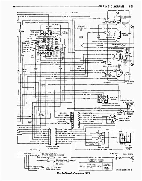
Jul 15, 2019 · In this video we show the location of the under hood fuse box on a vw passat. You can find the link on main channel page. Replace A Fuse 2012 2019 Volkswagen Passat 2012 Volkswagen Passat For 1998 vw passat v6 the fuse box is located on the left side of dashboard behind a plastic cover for left hand steering wheel vehicle. Most wiring diagrams for Winnebago 1986 Chieftain models will include color coding along with labeling to identify connections. Typically, each color indicates the magnitude or type of voltage, such as red for plus 12-volt connections, yellow for six-volt connections and black for ground connections. Also, most labeling and color coding will be ...Aug 8, 2021 · With Winnebago wiring diagrams, understanding the way your RV works can be made simpler. Winnebago wiring diagrams are designed to easily identify and locate the components within the RV. These diagrams are specially designed to provide the user with a comprehensive overview of the overall system. From major to minor, these diagrams provide ... Dec 6, 2017 · The type of wiring diagram you need to use depends on the job at hand. Tips for Using A Winnebago Wiring Diagram. When working with your 1988 Winnebago wiring diagram, it is important to keep a few basic tips in mind. First, make sure that you follow the directions for each step carefully. Careful examination of the entire diagram should be ... The Winnebago Wiring Diagram 5af725d346448 Gif 4 is a valuable resource for any Winnebago owner. It provides easy access to essential wiring information for the vehicle, allowing for quick identification of potential problems or areas of improvement.
2022 Wiring Diagrams. Era (100) 70A (Serial Number begins with 1516421) 70B (Serial Number begins with 1516521) 70X (Serial Number begins with 1517221) Travato (200) 59G (Serial Number begins with 1526221) 59GL (Serial Number begins with 1527221) 59K (Serial Number begins with 1526521)Dec 24, 2022 · Winnebago Wiring Diagram 5af725d346448 Gif 4 is a reliable and versatile wiring diagram for Winnebago vehicles. It is designed to provide quick and easy access to all the information needed to install and maintain the electrical system of any Winnebago motorhome or camper van. This diagram includes detailed descriptions of each component, step-by-step instructions, and helpful illustrations ...
Wiring Diagrams - Motorized R.V. Parts and Accessories Catalog (PDF) How to Identify a Motor home (PDF) Sealant Callout Sheets - Motorized Operator Manuals Paint Code Manuals - Motorized Audio/Video Guides - Motorized Supplier Links Click here Service Tips: Service Tips2005 Sightseer/Sunova D33L Wiring Diagram Book. ** Units manufactured before 4/30/04 utilize a Direct Contact Tank Level System and have a green circuit board on the monitor panel. Units manufactured after 4/30/04 utilize a Non-Contact Tank Level System and have a red circuit board on the monitor panel. Jan 5, 2020 · But what is missing on mine and yours, is a 12 volt wiring diagram. Location: Bremerton, Wa. The 12 volt installation plans just show where all of the 12 volt components are located. A 12 volt wiring diagram (if it were available) would show how the components were connected by the wires. May 30, 2021 · Posts: 259. 2020 Winnebago View Main Fuse keeps blowing. My main DC fuse in the battery tray keeps blowing killing all DC power to the house. This is the 3rd time it happened. When facing the battery tray, it is the far left fuse. The first time it blew, I replaced it with a same Littelfuse 100 amp slow blow fuse that was in there. They do. For instance, you can find in the Winnebago wiring diagrams, the exact layout and, location of the "Auxiliary Battery Boost" solenoid and, the "House battery disconnect solenoid". It labels them quite clearly. Not exactly a picture but, it's a PDF diagram that's pretty close to a picture.Research Genuine Winnebago Parts for your RV. Since 1958, Winnebago has been building the finest quality RVs in the industry. Our comprehensive 3D parts catalog can help you research the right parts. Parts Catalog.
Vista/Sunstar E35B Wiring Diagram Book. 110 Volt Load Center/Auto Transfer Switch. Battery Installation. Body, 110 Volt Wiring Installation/Diagram. Body, 12 Volt Wiring Installation. Chassis Electrical Box Assembly. Chassis Wiring Installation. Exterior Lamps Wiring Installation. Front End Wiring Installation. Holding Tank Monitor Panel ...
The Winnebago Wiring Diagram 5af725d346448 Gif 4 is one such diagram that helps ensure the smooth operation of the motorhome's electrical system. This diagram contains the information needed to make sure that all elements of the electrical system are working optimally, from the battery to the fuse box and beyond.
Paseo 848P Wiring Diagram Book. 110 Volt Load Center/Auto Transfer Switch. Body, 110 Volt Wiring Installation/Diagram. Body, 12 Volt Wiring Installation. Chassis Wiring Installation. Holding Tank Monitor Panel. Holding Tanks Wiring Diagram. TV Coax Wiring Diagram . Danger of electrical shock, burns or death.2002 Journey DL/Horizon P32TD Wiring Diagram Book. Danger of electrical shock, burns or death. Always remove all power sources before attempting any repair, service or diagnostic work. Power can be present from shore power, generator, inverter or battery. All power sources must be disabled and secured before performing any service. 2018 Wiring Diagrams. Era (100) 70A (Serial Number begins with 15164X1) 70A (Serial Number begins with 15164X2) 70B (Serial Number begins with 15165X2)Revel B44E Wiring Diagram Book. 110 Volt Load Center/Auto Transfer Switch. Battery Installation. Body, 110 Volt Wiring Installation/Diagram. Body, 12 Volt Wiring Installation. Chassis Wiring Installation. Holding Tank Monitor Panel tab - 03. Holding Tanks Wiring Diagram. TV Coax Wiring Diagram . Danger of electrical shock, burns or death.1988 Operator Manuals. To download the operator manual for your vehicle, simply click on the appropriate link below. This information is provided as a convenience to Winnebago Industries motor home owners. When your vehicle requires parts and/or service, you should contact your local Winnebago Industries dealer. Your dealer has access to the ...2009 Wiring Diagrams. Era (100) BD144U; BD170RL; BD170RT; BD170XL; BD170XT; Winnebago. Access (200) WF222B; WF224V; WF229T; WF231C; WF231J; WF231N; Outlook (300) WF329BUnderstanding the Winnebago Lesharo wiring diagram is the best way to get a better understanding of the electrical systems of your vehicle. Winnebago 1987 1989 Lesharo Service Manual Pdf Manualslib. Winnebago 1987 1989 Lesharo Manuals Manualslib. Winnebago 1987 1989 Lesharo Phasar Utility Van Service Manual Manualzz. Lesharorv View Article ...2013 Wiring Diagrams. Era (100). 70A; 70X; Winnebago. Access (200) 24V; 26Q; 31J; 31R; 31W; Access Premier (200) 26QP; 31JP; 31RP; 31WP; View (500) 24J; 24M; View ... Research Genuine Winnebago Parts for your RV. Since 1958, Winnebago has been building the finest quality RVs in the industry. Our comprehensive 3D parts catalog can help you research the right parts. Parts Catalog.
2005 Journey/Meridian P32T Wiring Diagram Book. 110 Volt Load Center/Auto Transfer Switch. AC/Heat/EMS Wiring Diagram. Antenna Installation, Radio and CB. Auto Lamps Wiring Diagram. Automotive Wiring Diagram. Backup Monitor Installation. Body, 110 Volt Wiring Diagram. Body, 110 Volt Wiring Installation. Body, 12 Volt Wiring Diagram. Body, 12 ... Posts: 4,845. The general wiring is: Battery: Black. Stoplight: Red. Ground: White. Brake: Blue. The stoplight wire goes to the switch on the brake pedal. Battery wire is fused for 20 Amp. Brake wire is generally Blue and goes to the bottom right terminal of a 7-pin RV connector or the middle pin of a 6-wire connector.2007 Wiring Diagrams. Winnebago. Access (200) WF222B; WF224V; WF226A; WF228P; WF229T; WF231C; Outlook (300) WF325F; WF327L; WF329B; WF331C; WF331H; View (500) WD523B Instagram:https://instagram. hands manure spreader parts diagramvictor allena virgini ready score chart 2022 Check out our Winnebago parts eBay store. Skip to content. Call to order: 800-933-7742. ... Wiring Diagrams; Plumbing Diagrams; Sealant Callout Sheets; Winnebago ... 1992 Wiring Diagrams. Winnebago . Minnie Winnie (400) WC422RG; WC424RC; WF427RC; WF427RQ; WF427RT; Minnie Winnie DL (500) WF522RG; WF524RC; WF527RC; WF527RQ; Brave (F) caryn seidman beckersan angelo craigslist cars and trucks by owner Posts: 4,845. The general wiring is: Battery: Black. Stoplight: Red. Ground: White. Brake: Blue. The stoplight wire goes to the switch on the brake pedal. Battery wire is fused for 20 Amp. Brake wire is generally Blue and goes to the bottom right terminal of a 7-pin RV connector or the middle pin of a 6-wire connector. furinno turn n tube AC/Heat/EMS Wiring Diagram. Auto Lamps Wiring Diagram. Automotive Wiring Diagram. Body, 110 Volt Wiring Diagram. Body, 110 Volt Wiring Installation. Body, 12 Volt Wiring Diagram. Body, 12 Volt Wiring Installation. Chassis Wiring Installation. Dash Radio Installation. Day Run Lamps Wiring Diagram. Exterior Lamps Wiring Installation. Front End ...First, that "hidden" manual breaker in the junction box is only 30A. That's what Winnebago's diagram says. I'm skeptical as I've run more than 30A to the battery before (but not by much). So maybe it's a 40 or 50. The other is that the 12v power from the tow vehicle (pin 4) has no protection at all to the battery.